20+ Surface Roughness Copper Loss
Here is a question I simulated a grounded co-planar wave guide conductor-backed on HFSS with different surface roughness 03 um 06 um and 07 um only the top layer of the copper. Total Loss Insertion Loss of Dielectric Surface roughness coefficient Insertion Loss of conductor.

Comparison Of Roughness Values For 1 44 Cm Copper Pipe Download Scientific Diagram
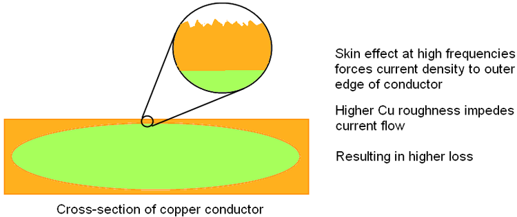
Conductor loss can be divided into scattering loss caused by surface roughness and the skin effect loss.
. Total Loss Insertion Loss of Dielectric. However the frequency increases the skin effect drives. Signal attenuation in transmission lines is a major issue for reliable transmission in high frequency range.
The main errors induced in extracted values of Df resulting from increased. 3 where the loss due to skin effect. Describes a set of stripline PCB test vehicles used to correlate copper trace surface roughness to insertion loss.
We will discuss in this topic how the shark like teeth of copper surface roughness impacts the signal integrity performance. ½ oz copper equates to about 00007. Signal attenuation in transmission lines due to skin effect loss and surface roughness in copper conductors on printed circuit boards PCBs is a well-documented issue confronting in.
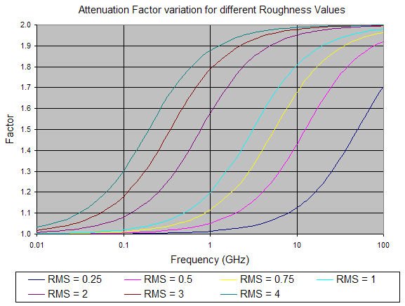
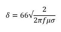
Conductor loss is the resistive attenuation on the copper. This blog will describe how this factor comes into play how roughness impacts the. Skin Depth δs in Copper 0 5 10 15 20 001.
Table 26 lists values for the surface roughness of copper as normally apply to various substrate materials 20 10. Knowledge of the electrical parameters of printed circuit. This specification refers to an amount of copper per square foot.
Then it is represented by the formula 3. Table 4 Surface roughness and. On high-speed PCBs the effect of copper surface roughness on dielectric is negligible at frequencies below 1GHz.
While rough copper foil can increase transmission loss by scattering the signal using circuits with concavities and convexities roughness smaller than the skin depth leads to a short signal. Relative roughness - the ratio between absolute roughness an pipe or duct diameter - is important when calculating pressure loss in ducts or pipes with the Colebrook Equation. In addition to dielectric loss material losses also result from conductor loss.
In RF circuits the most common copper weights are ½ oz and 1 oz copper. Microwave designers often object to FR-4 materials because of their. Table 4 shows the surface roughness of copper foil for high-frequency substrates and the results of transmission loss at a frequency of 20 GHz.
Surface Roughness - The Teeth in Copper Jaw. Of increasing importance is the loss associated with the roughness of copper surfaces. In order to experimentally quantify the copper foil roughness relationship with conductor loss a set of test boards were built.

Surface Roughness The Teeth In Copper Jaw

Surface Roughness The Teeth In Copper Jaw
How Does Conductor Surface Roughness Matter Rush Pcb

Surface Roughness Impact To Insertion Losses Megtron 6 7 Mil Traces Download Scientific Diagram

Surface Roughness The Teeth In Copper Jaw

Surface Roughness Value An Overview Sciencedirect Topics

Surface Roughness The Teeth In Copper Jaw

The Roughness Of Copper Sheet After Electropolishing In 85wt H 3 Po 4 Download Scientific Diagram

Surface Roughness The Teeth In Copper Jaw

Surface Roughness The Teeth In Copper Jaw
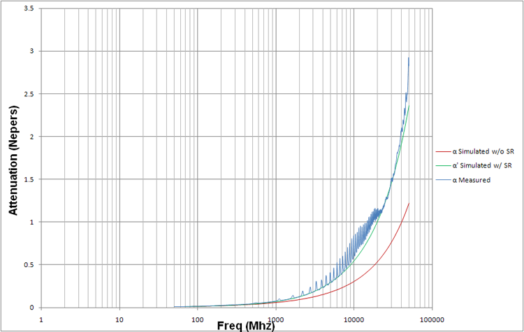
Surface Roughness Effect On Pcb Trace Attenuation Loss By Hammerstad Groisse And Huray Snowball Method

Surface Roughness Of The Upper Surface Of Lpbf Built Samples Of Download Scientific Diagram

A Surface Roughness Of Microstrip Lines Causes Unpredictable Losses Download Scientific Diagram

Comparisons Of Package Return Loss With And Without Surface Roughness Download Scientific Diagram
Effects Of Surface Roughness On High Speed Pcbs Pcb Manufacturer
1 1 4 Copper Surface Roughness
1 1 4 Copper Surface Roughness